Cart Pole System
Understanding and solving the Cart Pole problem using reinforcement learning and control theory
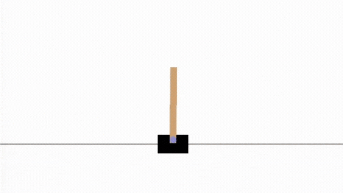
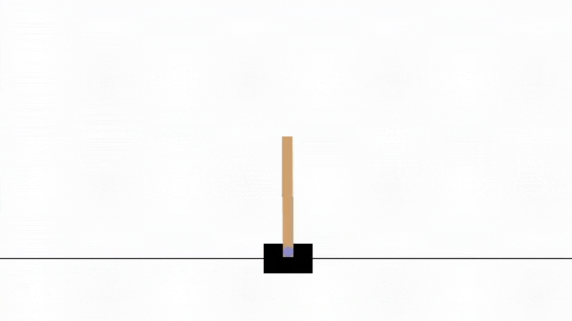
The Cart Pole is a very common system studied both in reinforcement learning and in control theory. In this problem, a pole is attached by an un-actuated joint to a cart, which moves along a frictionless track. The pendulum is placed upright on the cart and the goal is to balance the pole by applying forces in the left and right direction on the cart.
Today we will solve this problem using 2 different techniques:
- First, we will solve this problem using Proximal Policy Optimization (PPO), a famous reinforcement learning algorithm which is known to combine sample efficiency with stability.
- Secondly, we will solve this problem using a Proportional Integral Derivative (PID) controller, a control loop mechanism employing feedback that is widely used in industrial control systems.
Solving with Reinforcement Learning
I use the OpenAI Gymnasium API

Episodes conclude if the cart moves beyond a certain position range, the pole angle exceeds a specified value, or the episode length becomes excessive. Since the goal is to keep the pole upright for as long as possible, a reward of +1 is given for every step taken, including the termination step.
Now let’s find the good RL algorithm. First, we are dealing with a continuous state space, function approximation is therefore needed to learn the optimal policy (we could also discretize the state space, but we would loose some information). Since the landmark work by David Silver and colleagues in 2013 on using Deep Q-Networks (DQN) for playing Atari games
PPO is based on the Actor-Critic method. In its vanilla formulation, an actor network learns the policy and the critic network evaluates the chosen action by estimating their values (the expected future reward). Many algorithms follow this principle, such as TRPO (for Trust Region Policy Optimization)
You will find the code on my github. The general code structure was inspired by the OpenAI Spinning Up implementation of this algorithm, and I encourage you to read their article on PPO if you want to understand the key equations and have some insights on some important implementation tricks
Using Weight & Biases, we can plot some interesting data about the training of our agent. First, we can see that the actor loss and the critic loss both converge towards 0 in approximately 600 episodes. As the maximum episode length is set to 2000, we can see that from episode 500 the agent is maximizing the total sum of reward every episode.
")
")

Let’s plot the angle with respect to the time.

We can see that the agent policy is efficient as the pole angle \(\theta\) is stable and never exceeds +/-0.05rad, which we can observe by running the experiment:
Solving with Control Theory techniques
We will now solve the same problem using Control Theory. It is a field of control engineering and applied mathematics that deals with the control of dynamical systems in engineered processes and machines. The objective is to develop a model that manages system inputs to reach a desired state, minimizing delay, overshoot, and steady-state error, while ensuring stability in control. To achieve these results, a controller calculate an error value as the difference between a desired setpoint (SP) and a measure Process Variable (PV) and apply a correction based on this error. Today we will control the cart pole using a PID Controller (standing for Proportional-Integral-Derivative Controller), a control loop mechanism employing feedback that is widely used in industrial control systems.
Modeling the physical system
Before trying to control the system, we need to compute its transfer function. To this end, we need to get the equations of motion of the system.

System parameters are \(x\) the cart position, \(\theta\) the pendulum angle, \(F\) the force on the cart, \(m_c\) (the mass of the cart), \(m_p\) (the mass of the pole), \(g\) (the acceleration due to gravity), \(l\) (the semi-length of the pendulum arm), and \(I\) (the inertia of the pendulum arm).
I’ll spare you the most of the calculations, but if you’re interested you’ll find them here. Having posed the problem, we obtain the equations of the physical system:
\[\ddot{x} = \frac{1}{m_c + m_p} \left( F + m_p l \ddot{\theta} \cos{\theta} - m_p l \dot{\theta}^2 \sin{\theta} \right)\] \[\ddot{\theta} = \frac{3}{4 l} (\ddot{x} \cos{\theta} + g \sin{\theta})\]We start by linearizing them, using the small-angle approximation, to simplify their resolution.
\[\ddot{x} \approx \frac{1}{m_c + m_p} \left( F + m_p l \ddot{\theta} \cos{\theta} \right)\] \[\ddot{\theta} = \frac{3}{4 l} (\ddot{x} + g \theta )\]To further simplify the Cart Pole dynamical system, we use the Laplacian transform. Thanks to this transform, a linear differential equation can be represented by an algebraic equation, which makes it easier to solve:
\[\frac{\Theta(s)}{U(s)} = \frac{1}{\frac{l}{3}(4m_c + m_p)s^2 -(m_c + m_p)g}\]where \(\Theta(s)\) and \(U(s)\) are respectively the Laplacian transform of \(\theta\) and \(x\).
As the numerical value of the constant are given in the code of the CartPole environment, we compute the transfer function as follows:
\[\frac{1}{0.683p^2 - 10.78}\]Tuning the PID Controller with MATLAB
There are various methods to tune PID controllers, with one of the most renowned being the Ziegler-Nichols (ZN) method. This heuristic approach allows for empirical adjustment of the controller without requiring knowledge of the controlled system’s equations. In this project, we will use MATLAB, specifically the Control System Designer application, to tune the PID controller. Although the exact technique employed by MATLAB is not explicitly stated, it is known to be based on optimization methods. We start by specifying the transfer function:
Then, we tune the PID by using the Control System Designer app accessible via the command window with the function \(controlSystemDesigner(G)\).

After having tuned it, we get the PID coefficients by using the function pid(C).

Using these coefficient we can now easily implement the controller (the script can be find on the github given in the RL part). Let’s test the tuned PID on the cartpole system !
As you see the tuned PID seems efficient. We confirm it by plotting the pole angle with respect to the time.

We observe that the system continues to oscillate over time. This occurs because the environment is programmed to apply a fixed force to either the right or left at each step. Ideally, no force should be applied when the angle error is below a certain threshold to maintain a static system. Additionally, the applied force is set at 10N, and using a smaller force might help reduce the oscillations.
Better results could be achieved by fine-tuning the controller or by using alternative controllers such as Linear-Quadratic Regulator (LQR).